Tuesday, August 19, 2025

Elma TIPS: VPX System Integration — Where Should You Start?

 At Elma, we’re often asked: “I’ve got a VPX chassis and a set of VPX boards…can I just plug them in and power it up?”


The short answer: No.

The longer answer: It depends — but if you don’t verify compatibility first, you may be risking expensive damage.

While VPX (VITA 46) and OpenVPX (VIITA 65) standardize board and system level interoperability, when it comes to real-world implementation, there’s still a set of checks and balances to apply to system development.

With nearly four decades of experience supporting embedded computing platforms for defense, aerospace, and rugged industrial applications, we’ve seen just about every integration scenario — good, bad, and costly.

That’s why this installation of our Elma TIPS blog series focuses on the very first step in VPX system integration, profile compatibility, to hone in on some best practices and avoid headaches down the line.

The Importance of Starting Right

A common issue that still surprises us? Customers who receive a VPX chassis simply plug in boards without checking the profiles, and hope for the best. This kind of trial-and-error approach might work with consumer tech — but in VPX and SOSA® aligned* systems, mismatched profiles can result in damaged hardware or even catastrophic failure.

Module and Slot Profiles — The Foundation of a Successful Build

Every VPX module — also known as a plug-in card (PIC) — is built to a module profile defined by the VITA 65 OpenVPX specification. These profiles define:

• The pinout of the VPX connectors
• Supported protocols (e.g., PCIe, Ethernet, Serial RapidIO)
• Power distribution and grounding
• Optional user-defined I/O zones

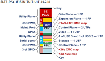
Likewise, each backplane slot has its own slot profile (Figure 1), specifying the types of signals it supports and how it connects to other slots in the system.

Press enter or click to view image in full size

Figure 1. Each backplane has a defined slot profile to indicate the signals it supports and how it connects within the system.

For integration to work as intended (and safely), the module profile must match the slot profile. (Figure 2)

Figure 2: The backplane topology diagram is important in system design to facilitate integration and debugging

Mismatched your PCIe lanes with Ethernet? They can’t communicate, and you might even damage driver and receiver circuits.

Mismatched the ground planes? You could permanently damage a $25,000 (or more) card before you even start your software development.

Your Integration Checklist

To avoid costly mistakes, follow this simple checklist when starting VPX system integration:

1. Know Your Module Profiles
Review each board’s datasheet or user manual. Reputable module vendors (and SOSA aligned ones in particular) will list the supported module profiles, often referencing the exact VITA 65 designation.

Press enter or click to view image in full size

Figure 3: Examples of compatible and incompatible sets of Module and Slot Profiles

2. Understand Your Backplane
Make sure you also have detailed datasheets for the backplane that, at a minimum, includes:
- Slot-by-slot profile information
Topology diagrams showing how slots are interconnected
- Supported signaling standards per slot

3. Consult the OpenVPX Specification
For instances where not all the information is available or a bit more clarity is needed, the VITA 65 standard is the definitive reference for profile definitions. It details all approved combinations, interface assignments, and mechanical constraints.

4. Ask for Help
Integration is rarely one-size-fits-all. At Elma, we’re accustomed to supporting customers at all stages of the game: during pre-development discussions, design reviews and post-deployment troubleshooting. If you’re not sure whether a board will work in a given slot, just ask us.

Common Pitfalls We See (So You Can Avoid Them)
• Skipping documentation — Don’t assume a board labeled “VPX” will work in any VPX slot. It’s not like USB, where it’s almost always safe to plug a device in.
• Overlooking ground and utility pins — These are just as critical as signal lines, especially in high-speed systems.
• Mixing SOSA aligned and non-aligned boards without proper planning — This can work, but only with proper analysis of backplane topology and signal compatibility.

Integration is a Process, not a Guess
Matching profiles isn’t optional, it’s fundamental. Get that right, and the rest of your system integration gets much smoother.
More than just offering a wide range of backplanes, chassis, and integration services aligned to the SOSA Technical Standard and VPX ecosystem, at Elma, we consider it part of our job to help our customers succeed — from identifying the basics to handling complex system integration. For more TIPS and insights on embedded system development, check out our other blogs.

*Note: the SOSA standard makes use of a specific set of VPX profiles for its hardware elements.

Just getting started with VPX? Watch our VPX Tutorials to learn the basics.

Tuesday, June 24, 2025

How Connectivity is Changing in the Face of SOSA

Connectivity is Key to the New Standard

As the SOSA Technical Standard progresses, the recent herculean efforts undertaken by the technical working groups have elevated the standard even further. The additions to Snapshot 3 further define system realizations in accordance with the MOSA directive from the DoD and other government agencies.

Although several factors in systems design, network speeds and power supply requirements have been examined and defined as the SOSA initiative nears its first release, one of the areas most impacted is connectivity. With SOSA Release 1.0 slated for mid-2021, it’s important to take a look at the evolution of the connectivity through Snapshots 1, 2 and 3, paying special attention to the accommodations made for speed increases and data throughput to meet the growing bandwidth needs of applications.

Network Needs in Systems Aligned to SOSA

Ethernet has evolved in its capability to allow for high speed, low latency transfer of data, and can now move data quickly with priority, replacing interfaces like PCI Express for data plane communication. It has become the primary network technology specified for use in SOSA systems. It supports many of the goals in SOSA including configurability, interoperability and is widely used. (Figure 1)

Figure 1: Communication takes place over IPMB bus and Ethernet via the Control Plane from the Plug-In Cards to the System Manager.
Figure 1: Example of a 3U Backplane Profile with Network Slot Profiles

In fact, SOSA relies extensively on Ethernet networks to pass information between SOSA modules, and currently supports high speed 1/10/40 Gb Ethernet (with 100 Gb in development) as well as low latency and deterministic transfer of data. High speed switches are used to implement Ethernet plug-in card switches.

SOSA systems are comprised of SOSA modules that must communicate. This means that SOSA module interconnects provide facilities to pass information between SOSA modules and physical network interconnects are defined to pass the information between SOSA plug-in cards.

Because the SOSA standard defines plug-in card hardware by OpenVPX VITA 65.0 and VITA 65.1, OpenVPX backplanes implement slots to accept plug-in cards and allow for interconnection between SOSA hardware entities to implement the necessary networks required in SOSA systems.

Network connections are implemented over the in the interconnected pipes found in the backplane, and the pipes are logically organized into various planes in OpenVPX. These connections may be physically implemented in copper in the backplane or externally via fiber optics.

System Requirements Defined by Industry Parameters

Although initial targets of the snapshots incorporated high degrees of network speed, as we prepare for the first release of SOSA, it’s evident that the need to meet these increasing throughout needs has resulted in shifts to the connectivity requirements in SOSA systems. (Figure 2).

SOSA network speeds by Snapshot
Figure 2: Increasing networks speeds have influenced performance attributes in SOSA aligned systems.

The need for this increased performance has influenced several connectivity design factors

  • A new VPX connector (TE’s RT3) was developed to support speeds of 25+ Gb/s
  • Module profiles were added to SOSA and OpenVPX to describe the required protocols
  • VITA 67.3 I/O connectors were updated to support RF contacts and fiber optic MT ferrules
  • Shift were made in slot profiles for payload & I/O-intensive SBCs as well as for switches and timing slots

Ensuring Connectivity as the SOSA Ecosystem Builds

Given the nature of SOSA, designed to foster interoperability across manufacturers and product technologies, ensuring connectivity within a system is critical.

One notable industry event that clearly demonstrated the strength of the SOSA ecosystem as well as helped validate the interoperability of the SOSA aligned components was the first Tri-Service Open Architecture Interoperability Demonstration (TSOA-ID) event for the media, acquisition community and industry influencers, hosted in January 2020 by the Georgia Tech Research Institute in Atlanta, Georgia.

Elma’s SOSA and CMOSS Aligned 12-Slot 3U Development Platform served as the heart of joint efforts by five SOSA Consortium member companies to build and test a fully functioning system aligned to SOSA. These industry partners, that participated in the demo using Elma’s development platforms included Behlman Power, Concurrent Technologies, Crossfield Technology, Curtiss Wright, Interface Concept and Spectranetix (a Pacific Defense company).

Connectivity needs in systems aligned to SOSA have kept pace with changing market demands, even during the initial stages of the standard’s development. Ensuring reliable throughput for high network speeds creates a path for continued strengthening of SOSA across all branches of the DoD.

Learn more in this informative webinar “How the SOSA Technical Standard Implements Highly Standardized, Configurable and Interoperable Network Communications Protocols”, hosted by Military & Aerospace Electronics, and experts from Elma Electronic, Interface Concept and Pentek.

Tuesday, June 10, 2025

Upgrades and Enhancements for Legacy VME and CPCI Ethernet Switches

 In the past few years, several end-of-life (EOL) announcements in the embedded computing market have both caused angst and opportunity. Making the shift away from a tried-and-true solution always brings with it the need to review not only the mechanical elements of an embedded system, but the integration and networking elements as well. And when that review is forced upon a designer, as in the case of an EOL announcement, it may mean forced choices of not-as-optimum alternatives. Or it could be something different altogether.

EOL is not the only option

One product segment particularly affected is high-performance embedded Ethernet switches in VME, CompactPCI, and VPX form factors. Component availability triggered board-level EOL notices, with some suppliers forced to reduce or eliminate product offerings in some of these form factors.

But others looked at this shift as a way to strengthen the Ethernet switch and add new capabilities by implementing a technology refresh to an existing product line, instead of just shutting production down or scaling back the availability of its switches. The ComEth product line by Interface Concept (sold in North America by Elma Electronic Inc.) is an example of this how lack of component availability does not need to result in an EOL announcement, but rather, can foster new opportunities to help ensure a strong embedded ecosystem.

How Ethernet speeds have evolved

Created in the early 1970s, Ethernet has seen many improvements and enhancements over the past several decades, with the speed of data flow increasing again and again. Today, Gigabit is considered the low-end, with many embedded systems requiring Ethernet connectivity speeds of 10, 25, 40, and even 100 Gigabit. It can even be faster than that, but 10 and 25 Gigabit SERDES lanes, which can be combined in groups of four to form fat pipes supporting 40 GigKr4 and 100 GigKr4, are commonplace in today’s embedded systems market.

In addition, these embedded systems often utilize Ethernet switches when more than a single point-to-point connection is required. The ComEth family of Ethernet switches is a good example of a modern switch that provides the high performance switching and routing features most desired by system integrators. This includes a feature rich switch management application called Switchware that lets the user configure an extensive list of parameters and configuration settings using either a convenient browser interface or Command Line Interface (CLI). Once a switch configuration is created, the configuration file is saved, exported and then loaded onto other switches, facilitating easy configuration across each switch.

System enhancements for VME & CompactPCI

Interfaces such as to VME and CPCI backplanes remain at 1000BaseT speeds due to the limitations of the backplane connectors, although other interfaces, like front panel ports, have been updated to support faster uplink speeds. For example, some ports that supported 1000BaseT in the past now offer a wide range of speeds up to 10 Gig-BaseT capability. Such ports often support 10 and 100 Megabit, Gigabit, 2.5, 5 and 10 Gigabit speeds.

This facilitates overall system enhancements, where other equipment in the system may also need to accommodate bandwidth increases. It is interesting that sometimes Gigabit is not fast enough and 10 Gigabit is more than enough, so these intermediate speeds of 2.5 and 5 Gigabit may help solve the problem of matching the switch’s speed to the needed bandwidth. There is also more use of SFP, SFP+, and QSFP ports, allowing users to select — and even mix — a variety of media interfaces.

Some systems require both copper and fiber of different speeds and a modern commercial-off-the-shelf (COTS) Ethernet switch allows the system integrator great flexibility to be compatible with higher-level system requirements. In some cases, even the need for quite old 100 Megabit fiber interfaces is still supported with these new designs for applications that must have it.

Backplane designs for VPX

In the VPX market, backplanes often utilize SERDES interfaces, which had been Gigabit or 10 Gigabit speeds for the past few years. With enhancements to VPX backplane designs and connector technology, new generation VPX form factor Ethernet switches now support speeds of Gigabit, 10 Gigabit and 25 Gigabit SERDES on a single lane and, when four lanes are combined into a fat-pipe,current products are supporting 40 GigKR4 and even 100 GigKr4 speeds, with more speed improvement on product roadmaps.

Enabling innovation instead of EOL shutdowns

Component availability is an issue we will be facing for a while, but by using this challenge as an innovation opportunity, embedded system designers can move towards new models of development to capitalize on computing technologies, like enhanced speeds in Ethernet switching, and improve system performance.

Browse the entire line of available Ethernet switches.

Tuesday, June 3, 2025

Factors of Increased Heat Generation in OpenVPX Systems

 It’s no secret that higher performance means higher thermal management
 requirements. Denser electronics packed into smaller spaces oftentimes leaves designers with the challenge of finding more creative ways to dissipate the increased amount of heat for conduction-type cooling methods.
 OpenVPX enables extraordinary leaps in aggregate system bandwidth and processing speeds that mandates new methods to meet the resulting thermal challenges.

OpenVPX has introduced optical and RF signals to the backplane, removing these otherwise discrete connectors from the front of the cards. While the new backplane connections eliminate what would otherwise be a jumble of cables, the aggregate high-speed signals that now traverse the backplane rapidly heat up the system, exacerbating the already difficult-to-manage temperature increases.

Some of the most complex cards are being used in applications such as signal intelligence for communications and to record signals on the battlefield — including enemy communications — taking in audio inputs and triangulating the source of enemy fire.

Many high-performance applications require processor and FPGA (Field-Programmable Gate Array) system bandwidth that drive up the thermal load on the inside the chassis, necessitating the need for new thermal management strategies. One example is a recent aerospace application that required many RF inputs — 36 payload slots each with 16 RF signals and many large radar arrays that require vast amounts of RF I/O signals.

Tight Spaces Mean More Heat

Embedded sub-systems must sometimes be packaged to fit existing tight spaces in aircraft, ground vehicles, submarines, spacecraft and other rugged, compact environments, and has led to the need for optimized SWaP-C (size, weight and power-cooling*). While OpenVPX offers significant improvements in field-deployed system signal integrity, speed and capability, it has created new challenges in these space-constrained installations.

As higher performance systems are implemented, the choice between 3U VPX and 6U VPX becomes a matter of what functionality can be packaged on the smaller card vs. the larger. And as processors and FPGAs enable more capability, the 3U VPX form factor is favored for its reduced size and weight. This pushes the existing convection and conduction cooling techniques defined by the standard to their limits.

That concentration of power in a smaller board has heavily impacted chassis and backplane designs and complicated thermal management in systems using a 3U card, making heat dissipation a larger issue. However, new cooling options under the VITA 48 umbrella are working to accommodate the increased heat in these high performance systems.

Beyond Traditional Convection and Conduction

Most current applications find conduction cooling, as defined by VITA 48.2, and its respected cohort convection cooling sufficient. But the added complexity and heat generation of new boards and connectors quickly push current system cooling methods beyond these defined limits.

As VPX has grown in popularity, the VITA standards committees have defined additional cooling methods under VITA 48 to ensure future thermal needs are adequately handled. Current iterations are:

  • 48.4, liquid flow-through, probably the most efficient up to 450 watts per card
  • 48.5, air flow-through, which has the advantage of being able to meter the air to specific cards
  • 48.7, air flow-by
  • 48.8, air flow-through cooling without sealing for small form factor 3U and 6U VPX modules (ANSI ratified October 2017)

The environment in which the boards will be developed and tested is typically different than the final deployed unit, so a lab chassis, for example, can usually rely on just fan cooling, whereas a deployed unit might need conduction cooling. The proper cooling method for a deployed system should be based on the most practical design and take into account the housing, the card heat sink and the chassis itself.

See blog post on VITA 48.4 and alternate cooling methods

OpenVPX into the Future

OpenVPX has allowed new definitions for VPX backplanes and systems, giving system architects and end users a far wider range of choices in critical high-speed applications, paving the way for more open architecture and multi-vendor interoperability in the future. It fosters technology growth over time, without requiring changes to system architecture. It uses adaptations within the standards themselves to enable new capabilities and build HPEC hardware.

System density is only increasing, and end users are still searching for ways to fit smaller boxes into more compact spaces, so they can put even more electronics into their applications. Which, or course, means more heat.Get more details and information on elma electronic

Wednesday, May 21, 2025

Artificial Intelligence (AI) Powers a New Era of Intelligent Embedded Computing

 AI-based computing is enabling multiple levels of insights and safety advancements throughout the embedded computing industry. We’re seeing a huge increase in a need for high computation systems that operate in challenging environments, and its AI-based platforms that can handle the processing requirements that enable object detection and tracking, video surveillance, target recognition and condition-based monitoring.

Operating systems based on AI computing provide optimized visualization capabilities to combine video and other vision sensors into one unified viewer application, which can subsequently be utilized for simultaneous localization and mapping of robots.

This sets the stage for more intuitive applications, such as human pose estimation to train robots to follow trajectories, which eventually can be used in autonomous navigation systems, as well as facial feature extraction in automated visual interpretation, human face recognition and tracking. These activities are designed to enhance security and surveillance, motion capture and augmented realty (AR).

Operational Intelligence Across Complex Environments

Complex GPGPU inference computing at the edge is enabling this visual intelligence, as well, including high-resolution sensor systems, movement tracking security systems, automatic target recognition, threat location detection and prediction. Areas like machine condition-based monitoring and predictive maintenance, semi-autonomous driving and driver advisory systems are also relying on the parallel processing architecture of GPGPU.

Much of the high compute processing taking place within these critical embedded systems relies on NVIDIA compact supercomputers and their associated CUDA cores and deep learning SDKs used to develop data-driven applications.  Traffic control, human-computer interaction, and visual surveillance well as rapid deployment of AI-based perception processing are all areas where data inputs can be turned into actionable intelligence.

Processing that Surpasses Convention

The NVIDIA Jetson AGX Xavier sets a new bar for compute density, energy efficiency and AI inferencing capabilities on edge devices. It is a quantum jump in intelligent machine processing, marrying the flexibility of an 8-core ARM processor with the sheer number crunching performance of 512 NVIDIA CUDA cores and 64 Tensor cores.

With its industry leading performance, power efficiency, integrated deep learning capabilities and rich I/O, Xavier enables emerging technologies with compute-intensive requirements. Elma’s new Jetsys-5320, for example, employs the Xavier module to meet the growing data processing needs of extremely rugged and mobile embedded computing application. It easily handles data-intensive computation tasks and provides for deep learning (DL) and machine learning (ML) operations in AI applications.

What’s Driving the Data Push

Speeds are increasing, causing board and backplane suppliers to produce new designs capable of 25 Gb/s per lane that support high speed PCIe Gen 3 and Gen 4 designs.  Sensors will also start to make use of 100 Gbe to transfer in and between chassis.

When a system is capable of running high performance deep learning-based inference engines, it can reliably perform advanced data and video processing tasks such as object detection and image segmentation of multiple video image streams captured through HD-SDI, Ethernet and USB3.0 cameras, and the like, interfaced through high-speed circular connectors.

Newer software environments will lead to replaceable accelerators and GPGPUs amongst suppliers. In open standards-based environments like The Open Group’s Sensor Open System Architecture™ (SOSA) initiative, high bandwidth local connections required between SBCs and GPGPUs, where two plug in cards (PICs) may form one SOSA module, may need to be scaled to meet growing data needs.

Rugged AI for Tomorrow’s Military Advantage

Today’s rugged embedded systems designers are craving mission-critical SFF autonomy with server-class AI processing to deploy in remote locations and overcome challenging connectivity. These systems need real-time responsiveness, minimal latency and low power consumption.  Advanced AI systems that facilitate data processing from the edge to across the cloud redefine the possibilities for using rugged, compact technologies in autonomous, harsh and mobile environments.

Wednesday, February 12, 2025

How to Design an Electronics Cabinet for Harsh Environments

 With the increasing tendency to place electronics systems in virtually any spot that will hold them, how environmental elements impact an embedded enclosure has become more important than ever. Regardless of whether you’re talking in terms of “rain, sun, air and dust” or “moisture, heat, humidity and contaminants”, managing increased exposure to external elements is something system developers need to consider.


And because embedded systems are being put into more remote applications, as well, many embedded designers are faced with mitigating levels and variations of these elements that they may not have faced before during a system’s development. Weighing how adversely each aspect will affect an enclosure will help determine which ruggedized elements are most critical.

Design considerations from the start

To properly design a cabinet for today’s harsh, applications, it makes sense to take stock of what your needs are, then weigh them against different options available in cabinet selection. Starting with these six critical considerations will help you define crucial parameters:

1) Strength-to-weight ratio:

What force will be exerted on this enclosure, and what material will need to be used in the construction? Are there other external elements to consider in the structure of the rack system?

2) Modularity:

What level of modularity and flexibility does your application require?

3) Thermal profile:

What are the ways in which your rack system can facilitate thermal management, and how varying will temperature spikes be across the life of the system?

4) Equipment accessibility:

How easy does access to your cabinet need to be in order to make adjustments, reach specific areas or swap out components? Design a system knowing where access points need to be.

5) Quality of construction:

Is your system exposed to temperature fluctuations, and will there also be corrosive elements, such as salt spray or contaminants? Will its construction withstand the long-term shock and vibration of the application?

6) Testing requirements:

Influencing factors in the evolution of cabinet construction

There are some trends in the electronics industry that have impacted what we are seeing today in terms of cabinets design for harsh environments.  

Denser computer systems: Those familiar with SWaP (size, weight and power) know how shrinking component size and increased system density has brought forth new dimensions of where and how electronics can serve a purpose. Placing computers in remote locations, and in finite spaces, has mandated the need for rack systems that make the best use of not just available space, but of the actual construction and features of the rack itself.

Image of cabinets designed for harsh environments, showcasing durability and specialized housing for equipment.
Figure 2: This rugged cabinet for shipborne applications includes shock isolators on the base and back of the unit

Cloud computing and IoT: By removing the need to house data onsite, cloud computing has redefined networked systems. No longer bound by physical locations and constraints, data freely moves through the air to find a home and foster collaboration and deeper insights among computing systems across the globe. In addition, edge computing is not only accepted, but expected, putting even tougher requirements on electronics housings to ensure they withstand a multitude of harsh environmental and mechanical impacts.

Flexible enclosure and cabinet solutions: From a practical standpoint, replicated, standardized environments are not the same as what you’d typically find in a central office or server room. Being able to construct a housing that fits the space and application needs, while ensuring these highly compact systems can reliably transfer large quantities of sensitive data is now a normal part of the development process.

Laying the groundwork for rugged cabinet design

Identifying application requirements upfront and owning up to the pitfalls that a system may be subjected to as well as knowing how to best meet environmental considerations will go a long way in developing the proper enclosure system.

First and foremost, determine the “what” and “what if” of the development process, instead of being an afterthought. The construction and design of your cabinet platform is just as important as the purpose and function of the electronics it holds.  

Learn more methods and considerations in our white paper titled "What to Consider When Selecting a Cabinet for Harsh Environments".

Tuesday, January 21, 2025

Elma Electronic

 Elma Electronic specializes in delivering advanced embedded computing solutions that include integrated chassis systems, modular enclosures, board products, VPX backplanes, and precision hardware components. With offerings in both standard and custom configurations, Elma caters to a wide range of industries, from defense and aerospace to telecommunications and medical technology. Known for reliability, long-term support, and exceptional technical expertise, Elma ensures that clients receive top-tier engineering solutions designed to meet the most demanding operational requirements while adhering to the SOSA standard.


Elma TIPS: VPX System Integration — Where Should You Start?

  At Elma, we’re often asked: “I’ve got a VPX chassis and a set of VPX boards…can I just plug them in and power it up?” ‍ The short answer: ...